
+86 18116360585
- English
- Chinese
- French
- German
- Portuguese
- Spanish
- Russian
- Japanese
- Korean
- Arabic
- Irish
- Greek
- Turkish
- Italian
- Danish
- Romanian
- Indonesian
- Czech
- Afrikaans
- Swedish
- Polish
- Basque
- Catalan
- Esperanto
- Hindi
- Lao
- Albanian
- Amharic
- Armenian
- Azerbaijani
- Belarusian
- Bengali
- Bosnian
- Bulgarian
- Cebuano
- Chichewa
- Corsican
- Croatian
- Dutch
- Estonian
- Filipino
- Finnish
- Frisian
- Galician
- Georgian
- Gujarati
- Hausa
- Hawaiian
- Hebrew
- Hmong
- Hungarian
- Icelandic
- Igbo
- Javanese
- Kannada
- Kazakh
- Khmer
- Kurdish
- Kyrgyz
- Latin
- Latvian
- Lithuanian
- Luxembou..
- Macedonian
- Malagasy
- Malay
- Malayalam
- Maltese
- Maori
- Marathi
- Mongolian
- Burmese
- Nepali
- Norwegian
- Pashto
- Persian
- Punjabi
- Serbian
- Sesotho
- Sinhala
- Slovak
- Slovenian
- Somali
- Samoan
- Scots Gaelic
- Shona
- Sindhi
- Sundanese
- Swahili
- Tajik
- Tamil
- Telugu
- Thai
- Ukrainian
- Urdu
- Uzbek
- Vietnamese
- Welsh
- Xhosa
- Yiddish
- Yoruba
- Zulu
- Kinyarwanda
- Tatar
- Oriya
- Turkmen
- Uyghur


A digital torque wrench measures applied torque electronically and presents the result on a screen. In a common strain-based design, loading the wrench causes a small elastic deformation in a sensing element. Strain gauges respond to that deformation, producing an electrical signal that the electronics condition, digitize and convert into a torque reading. The display is the final stage of this measurement process. Its target setting, live reading and retained peak can describe different things, so understanding where each value comes from helps explain what the tool is actually showing.
How Applied Torque Produces a Sensor Signal
Elastic Deformation Inside the Tool
Applying force to the handle creates torque about the fastener’s axis. Within the wrench, that load also produces a small deformation in the structure carrying it. A sensing element is designed to respond predictably within its operating range, allowing the instrument to relate its response to applied torque.
This is elastic deformation: the element tends to return to its original shape when the load is removed. It does not mean the wrench must bend visibly. The movement needed for measurement can be too small to see.
The mechanical arrangement varies between designs. A sensor may respond to bending or torsional strain, depending on how the tool carries and senses the load. The sensing element and gauge placement follow that mechanical design.
How a Strain Gauge Detects That Deformation
A bonded strain gauge changes electrical resistance as the surface beneath it stretches or compresses. Arranging gauges in a bridge circuit allows the measurement electronics to detect small resistance changes as a voltage difference.
The bridge output changes with the load on the sensing element. By measuring that response, the electronics can follow the torque being applied. The gauge itself does not need a pointer or visible movement to indicate the change.
At this point, the tool has an electrical response to loading. It does not yet have a finished number expressed in N·m.
How the Electronics Turn the Signal into Digital Data
Bridge Excitation, Amplification and Filtering
A bridge-based sensor needs electrical excitation so that its resistance changes can produce a measurable output. The resulting signal must then be suitable for the next stage of the measurement system.
Amplification brings a small signal into a useful range for measurement. Filtering helps control unwanted signal components, such as electrical noise, that could interfere with the result. Together with excitation, these functions prepare the sensor output for conversion.
These are functional stages, not necessarily separate components on a circuit board. Some devices combine several functions within an integrated circuit. Their implementation also involves choices about response speed and noise, so a clear display alone does not reveal how the underlying electronics process a changing load.
Analog-to-Digital Conversion
An analog-to-digital converter, or ADC, represents the conditioned electrical signal as numerical data. The processor can then use those data to calculate a torque value and manage the display.
Digitization makes the measurement available for numerical processing. The instrument can use successive measurements to update a live display, retain a measured peak or compare a reading with a selected target. The converter supplies the data; the processing determines how those data are used.
| Stage | What the measurement system handles | Purpose |
|---|---|---|
| Sensing element and strain gauges | Mechanical strain and resistance change | Detect the response to applied load |
| Signal conditioning | A small electrical signal | Supply excitation and prepare the signal for conversion |
| Analog-to-digital conversion | A conditioned voltage | Represent the signal numerically |
| Processing and display | Digital data and the measurement relationship | Present torque in the selected unit and display mode |
How Digital Data Becomes a Torque Reading
Relating the Sensor Output to Known Torque
The converter’s output is not inherently a value in newton-metres. The assembled measurement system needs a relationship between its electrical response and known torque.
That relationship allows the instrument to translate changes in sensor output into changes in indicated torque. Calibration compares the instrument’s indications with reference values under specified conditions. Where adjustment is necessary, it is a separate action; simply performing a calibration does not automatically correct an instrument.
The conversion may use stored coefficients or other processing appropriate to the design. Whatever the implementation, the relationship applies to the complete measurement system, from the loaded element through to the indication. A raw converter count becomes useful only when it is related to the quantity being measured.
Zero Offset and Engineering Units
A measurement system can have an offset: a nonzero output even when the intended applied load is zero. A zeroing function establishes the reference used for subsequent readings, following the tool’s instructions.
Zeroing and calibration address different questions. Establishing an unloaded zero does not demonstrate that the instrument reads correctly throughout its torque range. Offset describes the starting-point error; gain describes the scale of the response. Correcting the starting point alone does not establish the relationship across the measurement span.
Once the instrument has determined torque, it can express that quantity in a supported unit such as N·m or ft·lb. Changing the unit changes the numerical representation of the quantity. It does not create a different physical torque at the joint.
What the Display Shows During and After Tightening
Live Torque, Peak Torque and the Target Setting
A target setting is the value entered for an operation. A live reading represents measured torque as the load changes. A peak reading retains the highest measured value captured during the instrument’s defined measurement cycle.
Those values serve different purposes. The target tells the operator what value has been selected; it is not evidence that this torque has already been applied. A retained peak can remain visible after the force has been reduced, whereas a tracking display follows the changing measurement.
YouBar’s ratchet digital torque wrench lists PEAK and TRACK modes, P0–P9 torque presets, and audible and visual target alerts. These features describe how the tool presents and uses measurement information. An alert should not be interpreted as an automatic stop in applied force.
When reviewing YouBar’s digital torque wrench range, match those display functions to the information your operation needs. For requirements that go beyond the published specifications, discuss the measurement and display requirements for the particular model.
Previous News
Digital Torque Wrench for Spark Plugs: Range, S...Next News
Digital Torque Wrenches for Mini-Splits: Flare-...Feature Product
-
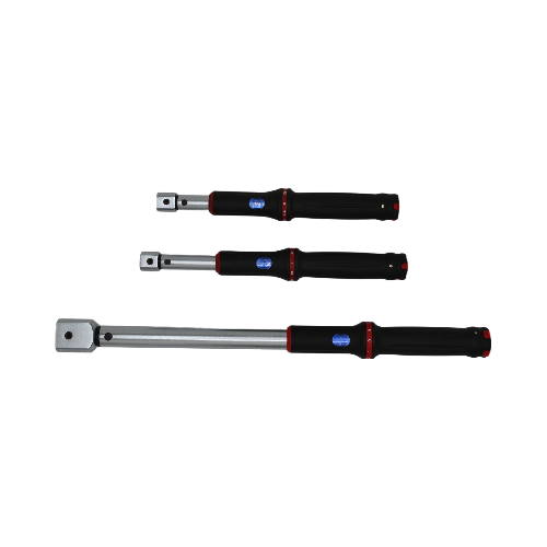 XS Series Interchangeable Head Window Style Cli...
TENGTUO ELECTRONIC TECHNOLOGY Item NO...
-
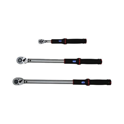 XS Series Window Style Click Torque Wrench
TENGTUO ELECTRONIC TECHNOLOGY Item NO...
-
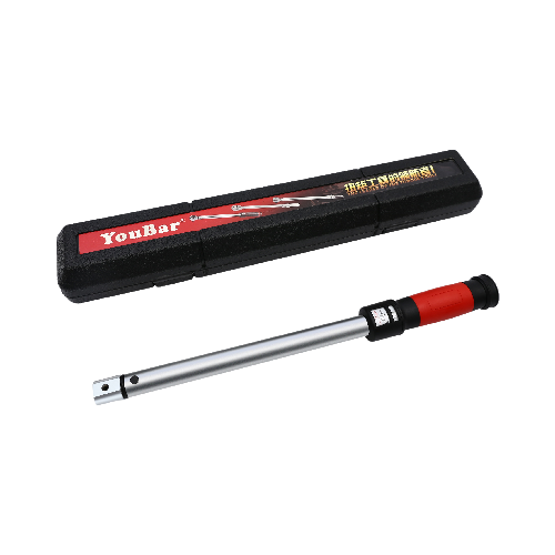 SL Series Interchangeable Head Window Style Cli...
TENGTUO ELECTRONIC TECHNOLOGY item NO...