
+86 18116360585
- Chinese
- French
- German
- Portuguese
- Spanish
- Russian
- Japanese
- Korean
- Arabic
- Irish
- Greek
- Turkish
- Italian
- Danish
- Romanian
- Indonesian
- Czech
- Afrikaans
- Swedish
- Polish
- Basque
- Catalan
- Esperanto
- Hindi
- Lao
- Albanian
- Amharic
- Armenian
- Azerbaijani
- Belarusian
- Bengali
- Bosnian
- Bulgarian
- Cebuano
- Chichewa
- Corsican
- Croatian
- Dutch
- Estonian
- Filipino
- Finnish
- Frisian
- Galician
- Georgian
- Gujarati
- Haitian
- Hausa
- Hawaiian
- Hebrew
- Hmong
- Hungarian
- Icelandic
- Igbo
- Javanese
- Kannada
- Kazakh
- Khmer
- Kurdish
- Kyrgyz
- Latin
- Latvian
- Lithuanian
- Luxembou..
- Macedonian
- Malagasy
- Malay
- Malayalam
- Maltese
- Maori
- Marathi
- Mongolian
- Burmese
- Nepali
- Norwegian
- Pashto
- Persian
- Punjabi
- Serbian
- Sesotho
- Sinhala
- Slovak
- Slovenian
- Somali
- Samoan
- Scots Gaelic
- Shona
- Sindhi
- Sundanese
- Swahili
- Tajik
- Tamil
- Telugu
- Thai
- Ukrainian
- Urdu
- Uzbek
- Vietnamese
- Welsh
- Xhosa
- Yiddish
- Yoruba
- Zulu
- Kinyarwanda
- Tatar
- Oriya
- Turkmen
- Uyghur


To calculate a torque wrench setting with an angled adapter, first determine how the adapter changes the tool’s effective lever arm. For a straight, rigid wrench-and-adapter arrangement used under the conditions described below, the corrected setting is the required fastener torque multiplied by the original effective length, divided by the new effective length. The adapter’s contribution depends on its orientation, not just its physical size.
That calculation has limits. An adapter angle is not the same as the additional bolt rotation specified in a torque-plus-angle tightening procedure. Nor does a correction formula establish the accuracy of an unverified tool combination. Start with the approved fastening requirement and the wrench manufacturer’s instructions, then calculate only for a configuration those instructions permit.
Which Angle Are You Calculating?
A crowfoot adapter connects the torque wrench drive to a fastener whose center is offset from that drive. Here, adapter angle describes the direction of that offset relative to the wrench’s longitudinal axis.
This is different from an instruction such as “tighten to the specified torque, then turn another 90°.” That instruction concerns fastener rotation during assembly. Positioning a crowfoot at 90° does not perform the additional quarter-turn, and an adapter calculator cannot replace the prescribed tightening sequence.
The practical question for this article is narrower: with the adapter installed in its intended working position, what torque value should be set on the wrench? Keep the fastener’s required torque unchanged. It is the wrench setting that may need correction.
Measure the Wrench and Adapter Before Calculating
A torque wrench angle calculator cannot resolve an incorrect dimension. Establish the reference points before entering any values.
Effective Wrench Length Is Not Overall Tool Length
Use the effective wrench length specified for the calculation by the tool manufacturer. In the conventional arrangement considered here, this is the distance from the square-drive center to the prescribed force-application point on the handle.
Do not substitute the distance from the front of the ratchet head to the end of the handle. A catalog dimension labeled “length” does not, by itself, identify the measurement needed for this calculation. Confirm the reference location and any model-specific measurement procedure.
Measure the Adapter Offset and Its Orientation
For a simple, rigid crowfoot, identify the center of the wrench drive and the center of the fastener. The center-to-center distance is the adapter offset. Its projection along the wrench axis determines the effective length change in the model below.
YOUBAR crowfoot wrench heads are square-drive open-end attachments relevant to this type of setup. When selecting one, confirm the drive interface, jaw size and dimension drawing. Do not treat an undefined catalog dimension as the required center distance.
| Input | Meaning in this calculation | Check before using it |
| Ttarget | Required torque at the fastener | Obtain it from the approved assembly or maintenance procedure. |
| L | Effective wrench length | Use the reference points and method specified for the wrench. |
| A | Drive-center-to-fastener-center distance | Confirm it from the actual geometry or an unambiguous drawing. |
| θ | Adapter orientation relative to the forward wrench axis | Define 0° as extending directly away from the handle. |
Use the same length unit for L and A. Millimeters with millimeters, or inches with inches, produce the same dimensionless correction ratio. Keep the torque unit consistent with the value you will enter on the wrench.
Calculate the Corrected Wrench Setting
The conventional effective-length correction is:
Tset = Ttarget × L ÷ (L + C)
Here, C is the change in effective length measured parallel to the wrench axis. For the simple planar geometry defined above, the projected length change is:
C = A × cos(θ)
Substituting that projection gives:
Tset = Ttarget × L ÷ [L + A × cos(θ)]
This form assumes a rigid, coplanar arrangement with the wrench head and handle aligned, force applied at the specified handle reference point, and the force direction perpendicular to the wrench axis. An engaged flex head, a different force direction or a more complex attachment requires its own approved method. The equations are a geometric explanation, not a YOUBAR-specific compensation specification.
The relationship follows directly from the lever arms in this model. The wrench setting corresponds to force multiplied by L, while the fastener torque corresponds to the same force multiplied by L + C. Eliminating the force gives the correction ratio.
When a forward-pointing adapter increases the effective length, the corrected setting is lower than the target fastener torque. This is not a recommendation to reduce the assembly’s torque requirement. It compensates for the additional leverage.
Before using a calculator, check its angle convention and whether it expects the complete center distance A or the already projected length C. Entering A into a field that expects C would give the wrong result at an intermediate angle. Set the calculator to degree mode when entering the example angles directly.
Compare 0°, 45° and 90° with the Same Setup
Consider a hypothetical calculation, not a specification or test result for a particular wrench:
- Required fastener torque: 100 N·m.
- Effective wrench length, L: 400 mm.
- Adapter center distance, A: 50 mm.
With those inputs held constant, changing the adapter orientation produces these theoretical settings:
| Adapter orientation | Projected length change, C | Calculated wrench setting |
| 0°, extending forward | 50.00 mm | 88.89 N·m |
| 45° | 35.36 mm | 91.88 N·m |
| 90° | 0.00 mm | 100.00 N·m |
At 0°, the calculation is 100 × 400 ÷ 450 = 88.89 N·m. Leaving the wrench set to 100 N·m would instead produce a theoretical fastener torque of 112.50 N·m in this idealized model. That shows why the unchanged setting is not appropriate simply because the adapter fits the drive.
At 45°, only the forward projection of the 50 mm offset is added. At 90°, that projection is zero, so this particular length correction disappears.
The 90° result applies to the defined geometry and loading conditions. It does not prove that every flex-head position, special offset tool or manner of applying force needs no correction.
The displayed decimal places show the arithmetic, not the achievable accuracy of the assembly. Select a permitted setting according to the actual wrench’s resolution and the approved work instruction. Do not round to a convenient number without checking whether the resulting setup meets the task’s requirements.
When the Standard Formula Is Not Enough
Interchangeable Inserts Use a Defined Reference Length
A removable insert fitted directly into a wrench body is not automatically equivalent to a crowfoot added to a square drive. An interchangeable-head wrench may be specified around a particular reference insert length. The relevant change is then the difference between the reference configuration and the installed configuration, using the manufacturer’s method.
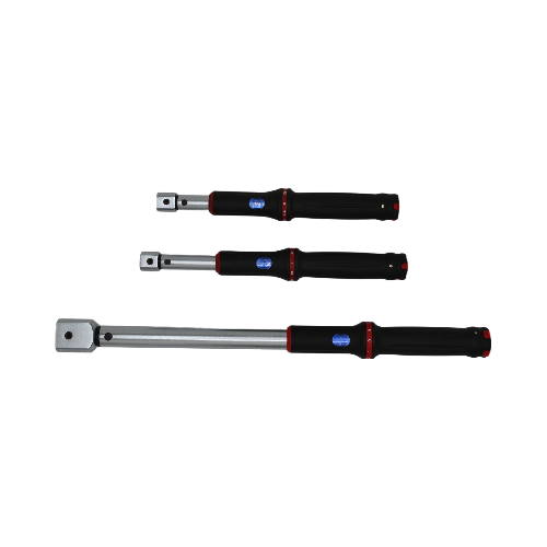
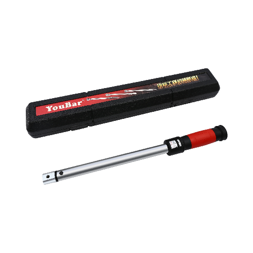
YOUBAR’s interchangeable-head digital torque wrenches represent a separate product architecture. Confirm the applicable reference length and insert combination rather than adding an entire head length to a dimension that may already include it. A matching interface alone does not establish the correct torque relationship.
Flex Heads and Built-In Compensation Need Separate Checks
Do not apply the straight-wrench formula unchanged to an articulated, non-coplanar or otherwise unverified configuration. Obtain the appropriate instructions or an approved verification method for the assembled tool.
Similarly, where a specific tool provides electronic length compensation, determine what its entered dimensions mean and whether the displayed target has already been corrected. Applying the same correction manually and electronically would count it twice. This is a model-specific check, not a claim that YOUBAR’s listed digital wrenches provide that function.
Check the Complete Setup Before Tightening
Treat the calculation as one part of configuration approval. Before use, confirm that the target comes from the correct fastening procedure, the recorded dimensions describe the actual assembly, and the calculated setting falls within the wrench’s applicable operating range.
Review the complete load path as well. In the hypothetical inline example, an 88.89 N·m wrench setting is intended to produce 100 N·m at the fastener. The lower setting does not mean that every attachment can be selected as though it carries only 88.89 N·m. Confirm each component’s suitability for its position and loading in the assembled configuration.
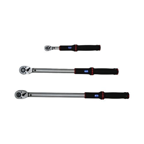
The published specifications for YOUBAR ratchet digital torque wrenches provide a starting point for comparing tool ranges and drives. They do not replace confirmation of the selected adapter geometry, effective length or complete setup.
Keep the approved configuration with the work instruction: wrench identification, adapter identification, effective dimensions, orientation, target fastener torque and corrected setting. Recheck the calculation when the tool or attachment changes, even if the new component has the same drive size.
The objective is not merely to obtain a number from a calculator. It is to connect that number to a defined, repeatable tool arrangement. To confirm a wrench and adapter configuration with YOUBAR, provide the tool and head models, a dimensioned drawing or clear geometry information, the intended orientation and the required fastener torque.
Previous News
Digital Torque Wrench Accuracy at 20–100 Nm: Wh...Next News
Digital Torque Wrenches with Data Output: What ...Feature Product
-
 XS Series Interchangeable Head Window Style Cli...
TENGTUO ELECTRONIC TECHNOLOGY Item NO...
-
 XS Series Window Style Click Torque Wrench
TENGTUO ELECTRONIC TECHNOLOGY Item NO...
-
 SL Series Interchangeable Head Window Style Cli...
TENGTUO ELECTRONIC TECHNOLOGY item NO...